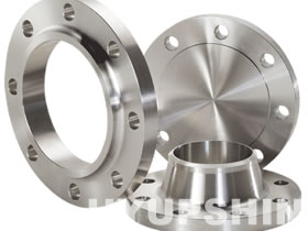
| ANSI (ASME) B16.47 SERIES A FLANGE (MSS SP44 FLANGE) |
 |
| CLASS 900 FLANGE / 900LBS FLANGE |
|
|
|
| Flange Dimensions & Approximate Masses / Flange Weight |
|
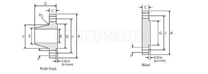
| ANSI B16.47 SERIES A CLASS 900 FLANGES DIMENSIONS TABLE |
Nom Size |
OD |
Thickness |
OD of RF |
Dia at Base |
Bore |
LTH |
Dia Bevel |
Drilling |
Weight |
Weld Neck |
Blind |
Bolt Circle |
Bolt Length |
Hole Dia |
# of Holes |
Weld Neck |
Blind |
|
O |
C |
C |
R |
X |
B |
Y |
A |
|
-1 |
-2 |
|
|
|
26 |
42.75 |
5.5 |
6.31 |
29.5 |
30.5 |
|
11.25 |
26 |
37.5 |
18.75 |
2.88 |
20 |
1525 |
2566 |
28 |
46 |
5.62 |
6.75 |
31.5 |
32.75 |
11.75 |
28 |
40.25 |
19.75 |
3.12 |
20 |
1810 |
3178 |
30 |
48.5 |
5.88 |
7.18 |
33.75 |
35 |
12.25 |
30 |
42.75 |
20.5 |
3.12 |
20 |
2120 |
3758 |
32 |
51.75 |
6.25 |
7.62 |
36 |
37.25 |
13 |
32 |
45.5 |
22 |
3.38 |
20 |
2545 |
4541 |
34 |
55 |
6.5 |
8.06 |
38 |
39.62 |
13.75 |
34 |
48.25 |
23 |
3.62 |
20 |
2970 |
5425 |
36 |
57.5 |
6.75 |
8.44 |
40.25 |
41.88 |
14.25 |
36 |
50.75 |
23.75 |
3.62 |
20 |
3395 |
6209 |
38 |
57.5 |
7.5 |
8.5 |
43.25 |
42.25 |
13.88 |
38 |
50.75 |
24.5 |
3.62 |
20 |
3385 |
6253 |
40 |
59.5 |
7.75 |
8.81 |
45.75 |
44.38 |
14.31 |
40 |
52.75 |
25 |
3.62 |
24 |
3620 |
6940 |
42 |
61.5 |
8.12 |
9.12 |
47.75 |
46.31 |
14.62 |
42 |
54.75 |
25.75 |
3.62 |
24 |
3960 |
7675 |
44 |
64.88 |
8.44 |
9.56 |
50 |
48.62 |
15.38 |
44 |
57.62 |
27 |
3.88 |
24 |
4300 |
8954 |
46 |
68.25 |
8.88 |
10.06 |
52.5 |
50.88 |
16.18 |
46 |
60.5 |
28.5 |
4.12 |
24 |
4640 |
10426 |
48 |
70.25 |
9.19 |
10.38 |
54.5 |
52.88 |
16.5 |
48 |
62.5 |
29 |
4.12 |
24 |
4980 |
11398 |
* Flange dimensions are in inches. Flange weights are in pounds.
* (1)- Flange Bolt lenghts are calculated based on bolting one WN to one Blind.
* (2)- Flange Bolt diameter should be 1/8" less than the bolt hole diameter
* Note:Larger sizes flange as well as intermediate sizes can be furnished.
|
|
| Production Capacity & Purchase Details |
|
|
| 1. |
Supply Flange Dimension DN15 - DN2000 (1/2" - 80"), Forged Flange. |
| 2. |
Material Carbon Steel: ASTM A105, A181, A350 LF1, A350LF2, A350LF3, A36, A234 WPB, Q235B, 20#, 20Mn etc. |
| 3. |
Material Stainless Steel: ASTM A182 F304, F304L, F316, F316L, F321 etc. |
| 4. |
Flanges Anti Rust: Anti Rust Oil, Black Paint, Yellow Paint Coating, Hot Dipped Galvanized, Cold Galvanized etc. |
| 5. |
Monthly Output: 3000 tons per Month. |
| 6. |
Delivery Terms: CIF, CFR, FOB, EXW. |
| 7. |
Payment Terms: Wire Transfer (T/T), Irrevocable L/C at Sight etc. |
| 8. |
Minimum Order Quantity: 1Ton or 100Pcs. |
| 9. |
Quality Guarantee: EN10204 3.1 Certificate, Mill Certificate, Third Party Inspection, Free Replacement Service. |
| 10. |
Find More Requirements In Flanges Market. |
|
|
| ANSI B16.47 FLANGE |
|
 |
|
| |
Search
ANSI / ASME B16.47 Series A Flanges
MSS SP-44 Flanges
Class 900, 26"-48"
|
|
|
|
|
|
|
|
|
|